XOR logic gate, diagram
Bildnummer 12918336
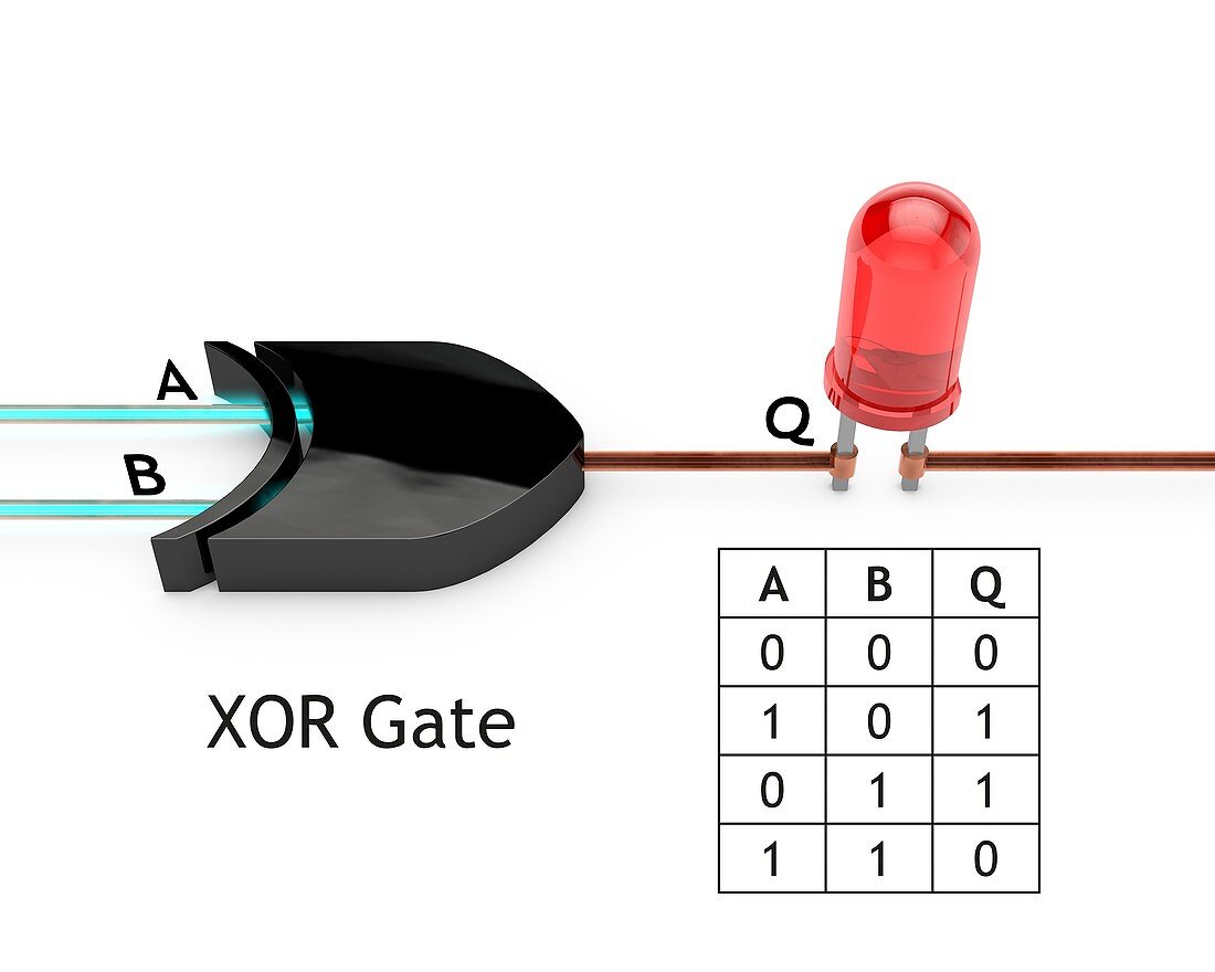
| XOR logic gate, diagram. Logic gates are electrical circuits that are wired so as to produce a specific output according to logical rules. The diagram shows two inputs (A and B) and an output (Q). The XOR (exclusive-OR) gate only outputs on if the inputs are different, as shown in the table at lower right. The inputs here are both on, with the LED (light-emitting diode) at right in the off (unlit) state. The shape of the logic gate shown here is that of the XOR symbol used on circuit diagrams. For a series of diagrams of the seven basic logic gates (NOT, OR, AND, NOR, NAND, XOR and XNOR), see images C045/9800 to C045/9806. | |
| Lizenzart: | Lizenzpflichtig |
| Credit: | Science Photo Library |
| Bildgröße: | 5123 px × 4098 px |
| Modell-Rechte: | nicht erforderlich |
| Eigentums-Rechte: | nicht erforderlich |
| Restrictions: | - |
Preise für dieses Bild ab 15 €
Universitäten & Organisationen
(Informationsmaterial Digital, Informationsmaterial Print, Lehrmaterial Digital etc.)
ab 15 €
Redaktionell
(Bücher, Bücher: Sach- und Fachliteratur, Digitale Medien (redaktionell) etc.)
ab 30 €
Werbung
(Anzeigen, Aussenwerbung, Digitale Medien, Fernsehwerbung, Karten, Werbemittel, Zeitschriften etc.)
ab 55 €
Handelsprodukte
(bedruckte Textilie, Kalender, Postkarte, Grußkarte, Verpackung etc.)
ab 75 €
Pauschalpreise
Rechtepakete für die unbeschränkte Bildnutzung in Print oder Online
ab 495 €